In this article we will briefly look at what RTP is and how it is used to stream VoIP audio. The article then considers how certain network transmission characteristics may introduce jitter or packet loss and the measures that are used in VoIP equipment to mitigate the effects. Other phenomenon which have a bearing on the audio quality on VoIP calls, along with the features used on VoIP equipment to overcome them, are also briefly discussed.
RTP
RTP is Real-time Transport Protocol. It is a general purpose protocol for the streaming of audio, video or any similar data over IP networks. In a VoIP call, each RTP packet carries a small sample of audio (typically 20 or 30ms) which is constructed by the sending device from analogue signals picked up by the microphone in the phone’s handset.
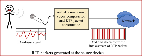
Within the RTP protocol, each packet must be numbered and time-stamped. This has to be done by the source device – the one that is sending the packets.
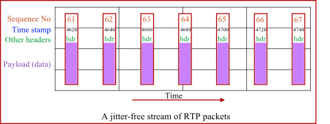
The presence of sequence numbers and time stamps allows the receiving device to inspect the packet headers and determine if the packets are arriving in the correct sequence, with constant or varying delay or if any are missing.
RTCP
RTCP is RTP Control Protocol. The protocol is used alongside RTP to provide reporting of the quality of the RTP stream being received at the far end of a connection. The RTCP packets are sent from time to time in the reverse direction of the RTP packets. RTCP packets contain data describing the quality of the RTP stream being received. They are sent to the sending equipment so it can know how good or bad the audio quality is at the other end of the line. Asterisk has some limited capabilities for users to view audio quality information at the command line. For example, you can try the commands “sip show channelstats” and “rtcp set stats on|off”. The following article talks a bit about call quality in the context of RTCP reports.
http://www.voip-info.org/wiki/view/Asterisk+RTCP
Jitter and packet loss
Jitter is all about the timing and the sequence of the arriving RTP packets. If they arrive in a nice steady stream at regular intervals in the correct sequence then you have low jitter. If they arrive in bursts interspersed with gaps, or if they arrive out of sequence, then you have high jitter. Jitter happens when the RTP packet stream traverses the network (LAN, WAN or Internet) because it has to share network capacity with other data. The following diagram illustrates how jitter can be created.
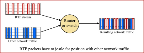
By the way, QoS (DSCP) is a way of marking packets so the intermediate network equipment is aware of their relative importance. QoS packet tagging allows the network equipment to prioritise one type of packet over another. For example, pushing newly received RTP packets through to the output interface in preference to other data packets, even if the other packets arrived first.
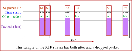
The following diagram illustrates what our original stream of RTP packets might look like after they have traversed the network, become jittered and arrived at the receiving equipment.
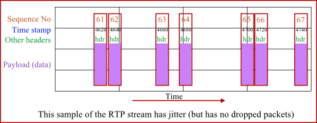
The variation in packet delay is generally referred to as jitter, although a more accurate description of this phenomenon is Packet Delay Variation (PDV).
http://en.wikipedia.org/wiki/Packet_delay_variation
The sequence numbering of RTP packets allows a receiving device at the far end to check if the packets are still in the correct sequence or if any are missing. Packets can get out of sequence if they take different routes over the network. Packets can be dropped if there is network congestion somewhere along the route or if there are network errors.
Jitter buffers
A jitter buffer is used at the receiving equipment to store incoming RTP packets, re-align them in terms of timing and check they are in the correct order. If some arrive slightly out-of-sequence then, provided it is large enough, the jitter buffer can put them back into the right sequence. However, for this to work the receiving device must delay the audio very slightly while it checks and reassembles the packet stream.
If a packet was dropped (or simply does not arrive in time) then the receiving device has somehow to “fill in” the gap using a process known as Packet Loss Concealment or PLC. Packet loss needs to be less than 1% if it is not to have too great an impact on call audio quality. Greater than 3% would certainly be noticeable as a degradation of quality.
Even if the RTP packets remain in the correct sequence and there is zero packet loss, large variations in the end-to-end transmission time for the packets may cause degradation of audio quality that can only really be fixed through the use of a jitter buffer.
Jitter buffers in Asterisk
Jitter buffering is not enabled in the default Asterisk configuration files. Enabling them is not as simple as you would hope because their activation is conditional on a number of different factors. First, you must enable the jitter buffers in the conf file relevant to the appropriate leg of your bridged calls. Typically this means in chan_dahdi.conf where you are using Asterisk to bridge between SIP and TDM circuits (you would think it would be in sip.conf, but apparently not). For SIP-to-SIP calls, Asterisk will often just let the jittered packets be forwarded as received, leaving it for the downstream end-point to de-jitter the stream. If you want to learn more about activation of Asterisk jitter buffers and PLC, look for chapter 15 in asterisk.pdf which you will find in the source install sub-directory /doc/tex.
Latency
Latency is simply a measure of the delay and it is measured in millisecond. Less than 140ms is almost undetectable to the human ear. Somewhere between 150ms and 200ms it begins to become perceptible and as the latency gets greater so it becomes more noticeable and more annoying.
There are several potential causes for latency (one of which is the use of large jitter buffers). Conversion between different codecs and the technology required to join SIP to TDM (or vice versa) will introduce small delays. There will also be a measurable time delay for packets to traverse the network – ping can be used to give a rough indication of the round trip time (time for a packet to get there and back), but ping is only a crude measure because network latency is influenced by packet type, packet size, QoS settings and by how congested the network is at any given moment.
Echo
Echo occurs when a user hears their own speech coming back to them and the total latency (including the return path) exceeds 150ms. If the time delay is low enough then the sound of your own voice does not cause much of a problem even at relatively high amplitude. In fact, some return sound in the earpiece of a phone is generally a good thing because it makes the handset feel “live”. This acceptable feedback is called sidetone in the telephony industry.
Echo cancellation is a large topic in its own right and there is not sufficient space to cover the subject in this article. If you want to understand it better some links are provided in the Further Reading section below.
Silence suppression, VAD and CNG
Silence suppression is a mechanism primarily designed to reduce network bandwidth demands, allowing VoIP equipment to send far less RTP data when the caller is not talking. The mechanism is defined in RFC3389. The source device uses Voice Activity Detection (VAD) to detect when the caller is speaking. During pauses in the speech it does not send audio samples in the RTP packets, but instead sends a special instruction showing that silence started or ended.
Ideally, the receiving device then needs to be able to regenerate suitable background noise to replace the missing audio – a mechanism called Comfort Noise Generation (CNG). Without CNG, the listener might find it very disconcerting to hear complete silence when the person at the other end of the line is not talking.
Echo suppressors and Noise cancelling microphones
Don’t confuse silence suppression and echo suppressors as they are not the same thing. An echo suppressor is used to reduce or prevent acoustic feedback on a speaker-phone. It does this by automatically reducing the microphone sensitivity whenever sound is coming out of the speaker. Conversely, it should reduce the speaker volume when there is no speech being played through the speaker. In effect it makes a speaker-phone operate in such a way that either the caller’s voice can be heard from the speaker or the local user’s voice is being picked up and transmitted by the microphone – never both at the same time.
A noise cancelling microphone is subtly different again. It automatically reduces its sensitivity when the user is not talking – in terms of gain characteristics it makes quiet things quieter and loud things louder. The idea is that you would use a noise cancelling microphone in a noisy environment like a call centre. When the agent stops speaking, the microphone rapidly adjusts itself to a lower sensitivity so it won’t pick up too much background noise. As soon as the agent starts speaking agin, the sensitivity will increase back to normal thereby making both the agent’s voice and the background noise louder.
MOS
MOS is a measure of audio quality that directly relates to the caller experience. It stands for Mean Opinion Score and was originally based on subjective opinions of people using a phone in controlled conditions. Now, in the VoIP world, it is used as a pseudo-objective measure allowing different levels of audio quality and speech clarity to be compared. A MOS of 3.0 is fair and of 4.0 is good. Wikipedia has a good article on this topic and the link is given below. It is interesting to note that the G729a codec can only deliver a MOS of about 3.9 whereas using G711 it can be as high as 4.5.
http://en.wikipedia.org/wiki/Mean_opinion_score
Further reading
An excellent overview covering many of the issues discussed here is given in an extract from a Cisco Press book here:
http://www.ciscopress.com/articles/article.asp?p=357102
Some articles that discuss issues of echo and echo cancellation in telephone circuits:
www.voipmechanic.com/echo-technical.htm
www.linuxjournal.com/article/8424
www.voip-info/wiki/view/Causes+of+Echo
Feedback – but not acoustic!
If you found this article useful, please take a moment to vote using the coloured buttons below. If the article did not meet your expectations, still feel free to vote, but also please leave me a comment so I know what to change or how to improve it later.


Extremely useful information, thanks.
Very useful article and nice explained.
Thx
if RF conditions are good but jitter and packet loss are very high, what is the solution ?
I don’t think I’m qualified to answer that question. The systems I work on all interconnect locally via cabled networks. When you say RF, I guess you’re working on mobile networks. I have no expertise in RF. Sorry. It’s a whole different area.
Good Job!
I have one question about jitter. In Asterisk how much time one rtp packet have to reach the destiny? and if one or more packets have lost in the middle of path the Asterisk could be broke the rtp stream and after this create a “one way audio” behavior?
Sorry about my poor english
thanks in advance!
Hi Felipe,
Jitter does not normally break the RTP path or cause 1-way audio. 1-way audio is almost always a result of NAT settings on the phone or on the firewall. If the firewall has “SIP ALG” option, then disable it. I have not yet found any SIP ALG that did not create more problems than it solved. If the phone has STUN option, then try enabling it.
Take a look at my other articles that discuss NAT problem:
https://kb.smartvox.co.uk/asterisk/asterisk-nat/
https://kb.smartvox.co.uk/voip-sip/sip-nat-problem/
https://kb.smartvox.co.uk/voip-sip/sip-devices-nat/
Regards.
John
Good article
Thanks
Hey thanks for the information, this is really helpful since I’m doing QoS of VOIP.
How much jitter is “too much”? In other words at what point does it become noticeable in VoIP conversations?
“Jitter” is not that easy to quantify because it encompasses several phenomena such as Packet Delay Variation, latency, packets arriving out of sequence and packet loss. The impact of PDV and of packets arriving out of sequence can be mitigated by using a jitter buffer, but at the expense of latency. Packets that were lost during tranmission – or arrive too late – may be replaced using PLC, but there are different algorithms for PLC and some sound better than others. So there is no simple answer to your question. That is why the article explains what would be noticeable for each issue: e.g. ideally packet loss should be less than 1%; but 3% would certainly be noticeable; latency less than 150ms; etc.
The ciscopress article (for which there is a link near the end of the article) includes various figures for tolerable values.
As with so many things in VoIP, the issues are complex and if you are looking for simplistic solutions and explanations, you may well be disappointed.
thanks for the info it is very useful
ich habe gute informationen hier festgestellt! Danke!