My previous two articles explored QoS tagging of voice data packets using ToS/DiffServ values and of Ethernet frames using CoS or Priority values. QoS is often advocated as an essential part of any self-respecting VoIP solution and there is no doubt it can make a big difference in the right circumstances. However, it would be a mistake to expect too much of QoS or to assume that it will always make a difference no matter what. To understand where and how it can help we need first to examine the underlying causes of network congestion – how and where it can happen.
What causes network congestion?
A network is a mesh of interconnected nodes. The nodes are pieces of network equipment, like routers and Ethernet switches, and the interconnections could be fibre optic or Ethernet (copper) cables.
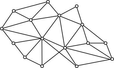
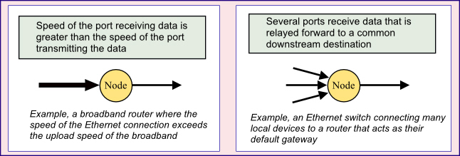
Let’s be clear, the data being transmitted over a single copper pair or fibre-optic cable all travel at the same speed – you do not get frames overtaking each other! So the points at which network congestion can occur are the nodes. Congestion happens at a node when the rate of ingress of data exceeds the rate at which the data can be forwarded to the next destination, the next node.
How does network equipment respond to congestion?
There are potentially several ways that the network equipment could deal with congestion and the actual method will depend in part on the capabilities of the equipment itself. For example, it might be possible for a downstream node to signal to the upstream node to stop sending for a while, to pause. This method is referred to as “flow control”.
Another option, if the router is able to detect congestion in a downstream route, then it might be able to send data via a different, less congested route. This would require quite a sophisticated device that is able to learn about alternative routes and evaluate them to choose the preferred route under different circumstances of network congestion. It would need to be able to read and interpret the Explicit Congestion Notifications coming back to it in the Layer 3 packets.
The mechanism that is of most interest to us now, however, is the prioritisation of packets or frames within the network equipment (the devices at the network nodes). As we will see, this is dependent on the presence of memory-based data buffers within the routing equipment, the management of virtual queues and algorithms that determine how data are assigned to and removed from the queues.
Flow control
Flow control is generally only possible with a full duplex interconnection. A flow control mechanism may take the form of a ‘PAUSE Frame’ in Layer 2 or an ‘ICMP Source Quench request’ in Layer 3. The concept is illustrated below:

However, flow control is not a complete solution and is not always possible. Consider, for example, the case of a media stream carrying voice or video – such data is time-critical and cannot therefore tolerate significant interruptions. Indeed, if flow control is not going to simply push the problem back onto other upstream nodes, then the flow control signal would have to be sent all the way back to the original source that is sending the data. That may not be possible and, even if it is, the source may simply not be able to pause – the ultimate source for an audio media stream is the person speaking and they are hardly likely to be controlled by a flow control signal in the network.
Memory buffers
No matter which mechanisms are used to manage congestion, there is an inescapable necessity for the network equipment at each node to have some form of memory-based buffering. Buffering allows it to receive data and decide how to handle it before sending it on to the next node. Without buffering, any situation where data are being received at the equipment faster than they can be transmitted out the other end has only one option: the “excess” must be discarded (so called ‘packet loss’).
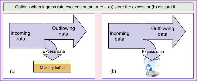
All network equipment, beyond a simple hub, must therefore have some memory buffering. Furthermore, the core mechanism for discrimination and prioritisation of network traffic works by using these internal buffers to queue the data.
On a very basic router or switch the memory buffer would be quite small without being sub-divided – it would behave as a simple queue where new data are added to the back of the queue while the older data at the front of the queue gets processed (so-called FIFO). On the more sophisticated and expensive boxes the buffers are larger and are sub-divided into multiple queues – as new data packets arrive they are assigned to the back of the most appropriate queue depending on their QoS settings.
The software running on the router takes packets from the front of each queue in a pre-defined way that allows some queues to have a higher priority than others. The algorithms used to process these queues have to be clever enough to take account of preferences for low latency and risk of packet loss – basically trying to prioritise some queues while avoiding the risk that the lowest priority queues never get a look-in. If the buffers are getting full, flow control would be attempted. Failing that, when packets have to be discarded, the algorithms might look at the QoS settings to determine the drop priority and thereby choose which ones to drop.
Limitations of memory-based buffering
While buffering of data is essential and is integral to the prioritisation of network traffic and the general management of bandwidth, it is not a panacea. In fact, the more that buffering is used, the greater the latency (delay). Furthermore, while buffering may help to avoid packet loss, it cannot prevent it if the ingress rate at a node exceeds the outflow rate for a long period of time. In effect, the buffering just helps to smooth out short-term peaks by time-shifting the excess input at one point in time to a quieter period a little later.
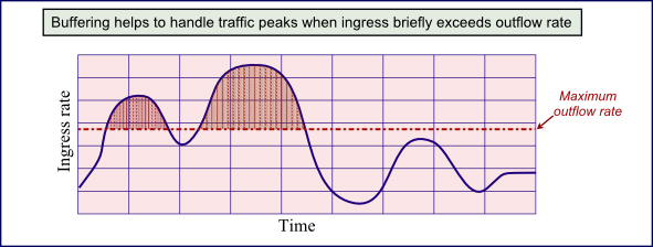
The shaded area of the graph, where inbound transmission rates exceed the maximum outflow rate, equates to data that must be temporarily put into the buffer. Only when the inbound rate drops below the dotted red line is it possible for the equipment to empty its buffers. If the rate stays above the red line for too long, then the buffers would become full and packets would have to be dropped.
The implications for practical application of VoIP QoS
We need to draw some conclusions from this exploration of network congestion issues. What does it mean in practical terms for VoIP system designers and IP-PBX installers? Based on the above points and also drawing upon my own experience of real-world installations, I would suggest that the following conclusions can be drawn:
- Network congestion happens at nodes where the data ingress rate exceeds the outflow rate. If this ‘speed’ disparity exists for too long, then packet loss is likely to occur. If there is no congestion then QoS is more or less irrelevant.
- QoS influences how network congestion is handled. It can determine which packets are most likely to be dropped if buffers get full and it can influence the latency (delay) of certain data streams by prioritising one stream with respect to another.
- Network equipment may allow a fixed proportion of the overall bandwidth to be set aside for a particular QoS class of traffic – this type of bandwidth management will normally allow lower priority data to “borrow” some of the reserved bandwidth when the high priority traffic is not using it.
- Just using QoS settings to mark packets or frames as “high priority” as they leave your IP phone or IP-PBX, guarantees absolutely nothing about how they will be handled.
- Effective bandwidth management is possible within your LAN or corporate WAN where you have control over the topology of the network, the choice of equipment and its configuration. The network equipment must support traffic shaping or traffic prioritisation and be configured to recognise and use your chosen QoS tags such as DiffServ or CoS.
- Once network traffic goes outside your own network infrastructure it is quite likely that QoS tags will be overwritten or ignored. This is especially true when traffic leaves your premises to traverse the Internet using an ordinary broadband connection. If you need end-to-end real time QoS over a broadband Internet connection you will need to look closely at the packages being offered by different service providers and you must expect to pay a premium for a broadband connection that supports it.
- In most cases, QoS is far more relevant to transmissions in one direction than in the other. For example, if network congestion is happening at a node because the outbound connection is slower than the inward one then the chances are that for data travelling the other way there will be no problem. Furthermore, you may be able to set the QoS tags on packets you are sending, but you may not be able to set it on the ones you are receiving.
- Bandwidth management is a multi-faceted problem: there may be trade-offs between decreasing latency vs increasing packet loss; getting faster throughput of voice almost certainly means there will be times when there is slower throughput for other data and could even result in packet loss for other data.
Topics for further discussion and reading
If time permits, I will write a follow-up article looking at how bandwidth management works in practice; in particular how prioritisation using QoS is generally implemented within a network switch or router. If you want further reading, a good starting point is wikipedia and Google – try looking up the following topics: dropped packets, latency, jitter, weighted fair queuing, QoS.
I recommend you download and read the white paper written by Berni Gardiner and freely available for downloading from this link . Berni is a certified Cisco instructor with 30+ year’s experience in networking and his white paper provides a great, easy-to-read intro to the topic.

Good read, well explained .
Very good articule, simple but all explained.